Polarisation Index Motor Insulation Test Uk
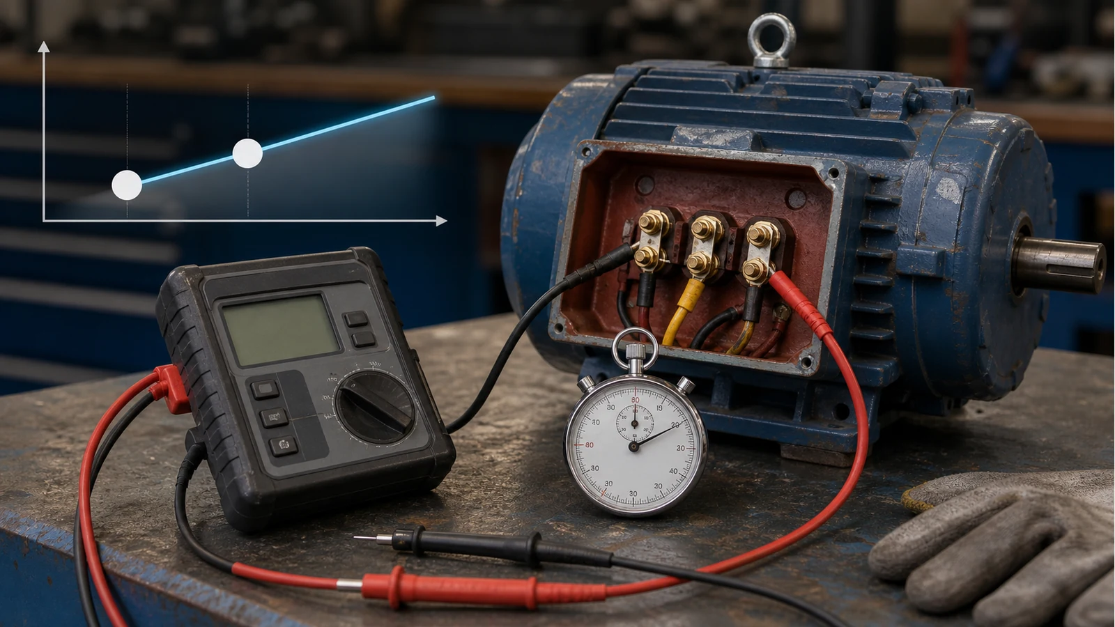
Direct answer: polarisation index, or PI, is the 10-minute insulation resistance reading divided by the 1-minute reading during the same DC test. It can help motor teams distinguish clean, dry insulation from moisture or surface leakage trends, but it is not suitable for every motor and it is not automatically built into every megohmmeter.
PI is useful because it looks at how the reading changes over time, not just the first number on the display. A damp or contaminated winding can flatten the curve because leakage dominates. A clean insulation system often shows a rising reading as absorption current decays.
The Formula
Contractors Unlimited's polarisation index note gives the simple field formula: PI equals the 10-minute insulation resistance divided by the 1-minute insulation resistance. In a job sheet, write it as PI = R10 / R1. Keep both readings in the record; the ratio alone is not enough context.
Manual Timed Procedure
- Isolate the motor, lock out, prove dead and disconnect equipment that may affect the test.
- Select the test voltage from the motor rating, manufacturer data and site method.
- Confirm the winding is discharged before starting.
- Apply DC test voltage and record R1 at 60 seconds.
- Keep the test running and record R10 at 10 minutes.
- Remove voltage and discharge the winding for the required time before touching terminals.
InsulationTesting.com's IEEE 43 motor guide explains the wider motor context: test voltage selection, timed readings, discharge and the limitations of the measurement. The important point for a UK workshop is discipline. If one technician records at 50 seconds and another at 70 seconds, the trend becomes less useful.
When PI Helps
PI is worth considering after damp-weather trips, long storage, washdown events, rewind drying, or when a large motor has enough insulation system to make timed behaviour meaningful. It is especially useful when you have a previous comparable test: same voltage, similar temperature context and a known connection pattern.
PI can also stop a team from trusting a single spot reading too quickly. A first reading may look acceptable, but a flat or weak rise over 10 minutes can point towards contamination or moisture that deserves more investigation before re-energising.
When PI Is The Wrong Tool
Do not force PI onto every small random-wound motor. Some insulation systems reach their useful timed change early, and some high-resistance readings are already so high that the calculated ratio becomes unstable or unhelpful. Treat PI as one diagnostic method, not a universal pass stamp.
A basic digital megohmmeter can support manual R1 and R10 readings if the display is stable and the operator times the test. That is different from claiming the instrument has automated PI, DAR, memory or report export. If your customer report requires automated PI output or a traceable instrument certificate, choose equipment and paperwork for that requirement first.
Job-Pack Wording
A practical job pack should say: motor ID, winding access, disconnected accessories, test voltage, R1 time, R10 time, temperature notes, discharge method, acceptance authority and what to do if the PI is low or not applicable. That last item matters. If the motor type makes PI unsuitable, record why and use the correct alternative from the site standard.
For choosing the voltage, use the UK insulation test voltage guide. For motor-shop staging, use the motor rewind shop workflow.